

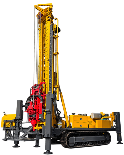
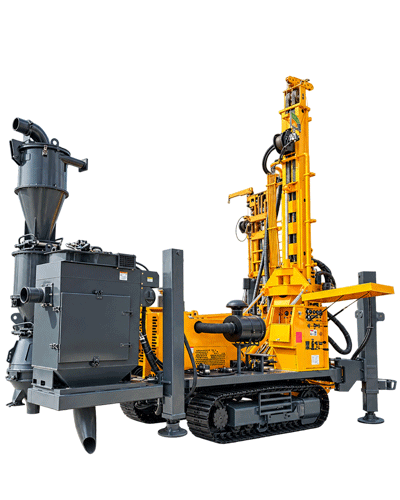
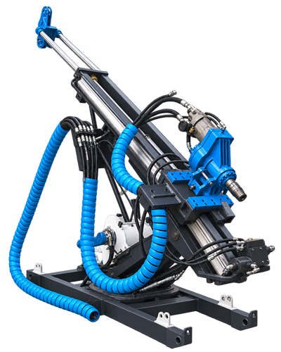
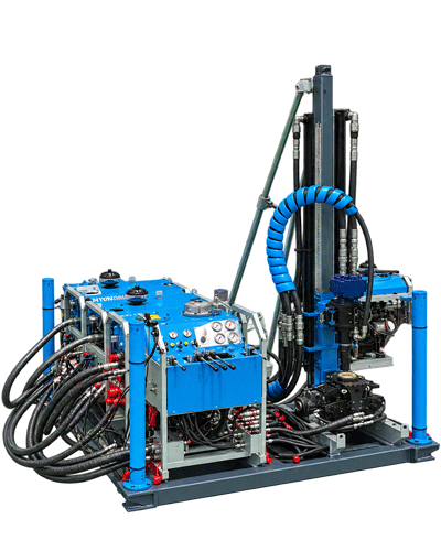
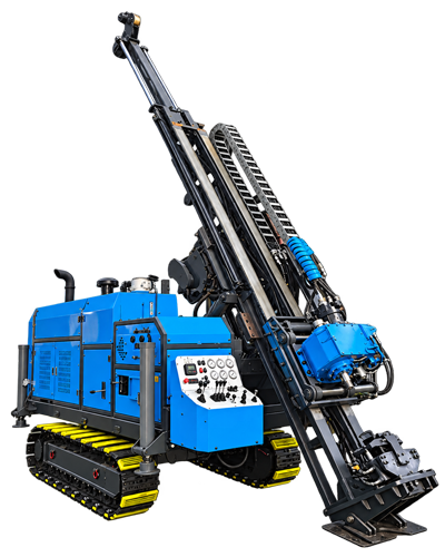
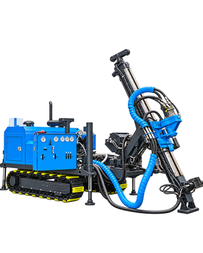
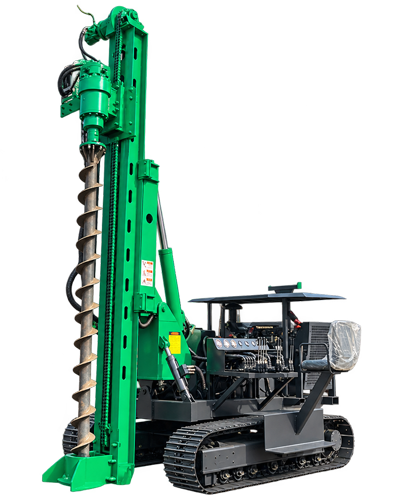
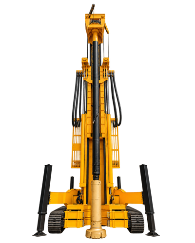
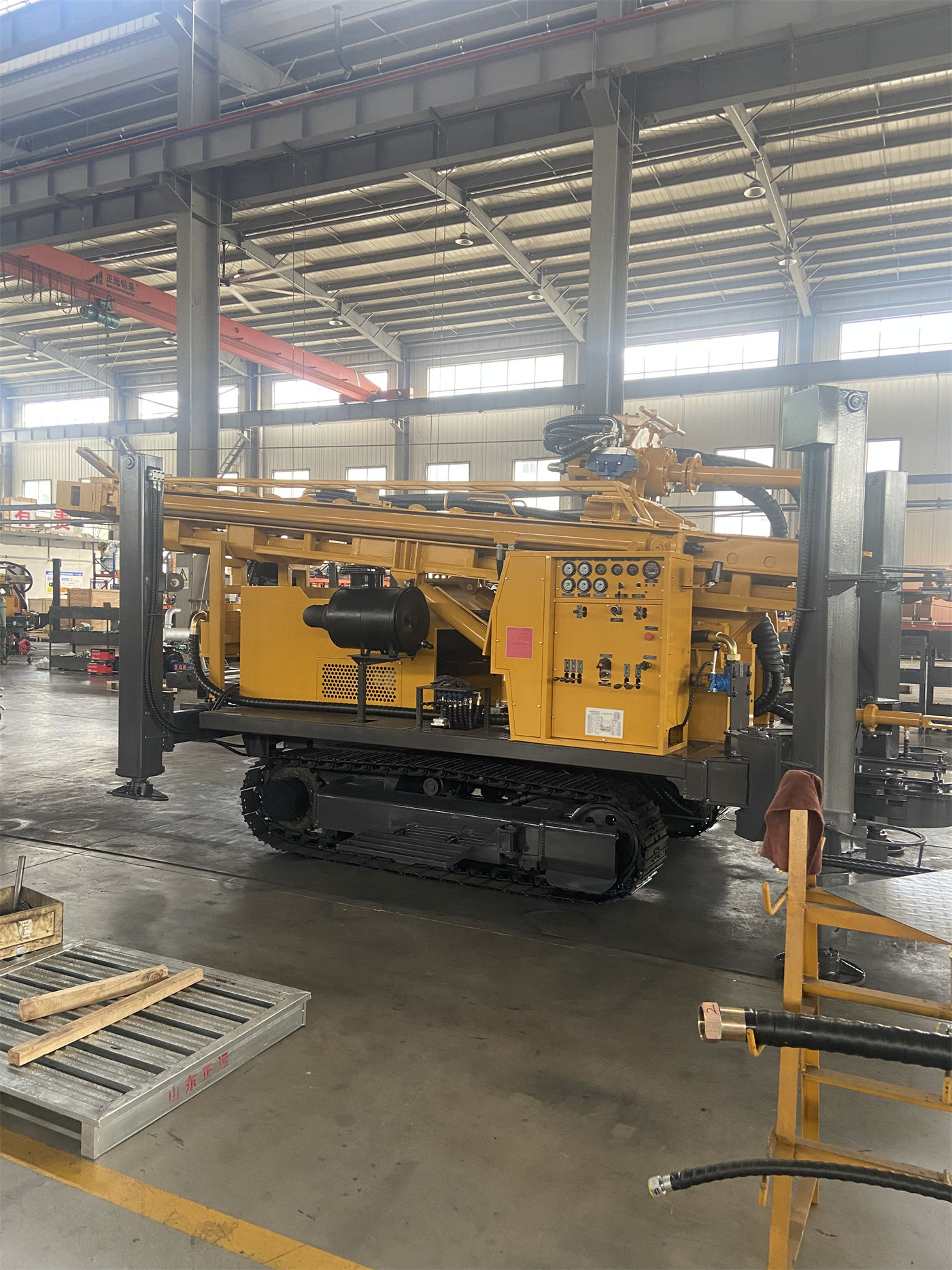
When looking at water well drilling rig documentation, power and hole diameter are often the first two lines scanned. The former states 73 kW or 85 kW, and the latter states 105–325 mm. The numbers themselves are not difficult to understand; the difficulty lies in judging which end of these two lines to choose for one's own project. The configuration orientation of a 300-meter-class crawler water well drilling rig is not about taking the maximum of both lines to be safe; if the power is selected too high and the hole diameter is set too wide, the equipment investment and supporting burden will also increase.
This article uses the public information of the WR300SE as an example and follows the order of "first look at the operating objectives, then look at what conditions each of the two lines of data corresponds to, and finally list the supporting equipment and boundaries" to explain how to read these two lines and how to judge the configuration orientation.
First determine the hole diameter: it is the result of well completion design, not the upper limit of equipment capability
The drilling diameter of the WR300SE is specified as 105–325 mm. This range is the scope the equipment can cover, which does not mean that a certain value in the middle is directly taken on site. The completion hole diameter is jointly determined by several factors: the designed water yield, the outer diameter of the well casing, the size of the submersible pump, the stability of the upper loose layer, and whether casing is needed to protect the wall.
The documentation clearly states that the final hole diameter should be determined based on the designed water yield, well casing size, and formation stability. The opening hole diameter usually needs to be larger than the outer diameter of the well casing to facilitate casing installation and gravel packing; in loose layers, sand layers, and gravel layers, if the borehole wall stability is poor, space for wall protection and casing also needs to be reserved. In other words, the hole diameter line should come after the "well completion structure design," not as the first basis for equipment inquiry.
Conversely, the upper limit of 325 mm indicates a boundary: when the well diameter requirement exceeds this range, the coverage capability of this equipment is at its end, and equipment with a larger hole diameter class needs to be used. The documentation does not explain the specific construction method beyond 325 mm, so no inference is made here.
Next look at power: 73 kW and 85 kW correspond to differences in load conditions
The standard power of the WR300SE is 73 kW, with 85 kW as an optional configuration. The judgment clue given in the documentation is: for projects mainly involving conventional hole diameters and general formations, the standard power helps control equipment costs; if the project is long-term under conditions of larger hole diameters, hard rock, or high altitude, a higher power configuration can be evaluated.
This means that the power line cannot be selected separately from the hole diameter and formation. When the same equipment drills 105 mm and 325 mm, the rotary load of the drilling tools, the requirements for cuttings removal, and the penetration resistance are all different; when using a down-the-hole hammer in weathered rock or intact rock formations, the air consumption of the air compressor and the impact demand will also change the overall load of the machine. The documentation groups "larger hole diameters, hard rock, high altitude" together because all of these push up the power requirement, not because they are equivalent to each other.
Another layer to distinguish is: engine power is not directly equal to rotary torque. The maximum rotary torque of the WR300SE is 7000 / 3500 N·m, corresponding to a maximum rotary speed of 80 / 160 r/min, which is a dual-condition setting. The lower speed and high torque state corresponds to larger hole diameters and higher loads, while the higher speed state is used for drilling stages with less resistance. Power options and torque conditions are two different levels of configuration and should not be mixed into one line when judging.
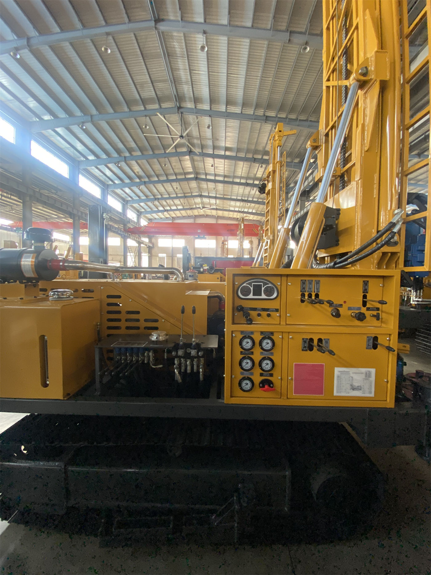
Only by putting the two lines back into the same project can the configuration orientation have a basis
The following uses hypothetical scenarios to illustrate the judgment sequence and does not represent the choice or construction result of any actual customer.
- Assume an irrigation well project is planned with a well depth of around 250 meters, a relatively small completion casing, and a moderate designed water yield, with clay and sand layers in the upper part and weathered rock in the lower part. According to the documentation, the hole diameter requirement falls in the middle-to-lower part of the 105–325 mm range, and the power can first be evaluated with the standard 73 kW configuration; if a down-the-hole hammer is switched to after entering the rock formation, the matching of the air compressor pressure of 1.2–3.5 MPa and air consumption of 16–55 m³/min also needs to be checked.
- Assume another project has a well depth close to 300 meters, a relatively large completion hole diameter, and the hole section is in hard rock for a long time. Under such conditions, large hole diameter and hard rock are superimposed, and the load is relatively high; the documentation suggests that the 85 kW configuration can be evaluated. However, power is only one item; the lifting force of 15 T, drill pipe diameter of 89 / 102 mm, and whether the air compressor displacement can keep up all need to be checked together.
- Assume the hole location is in a high-altitude area. The documentation lists high altitude as one of the conditions for evaluating a higher power configuration but does not give a specific correspondence between altitude and power. Such projects need to confirm derating conditions with the manufacturer and cannot be estimated solely based on plain parameters.
Beyond the two lines of data, several supporting items will in turn constrain the configuration
Setting a wide hole diameter not only changes the rotary load but also increases the requirements for cuttings removal and wall protection. In the documentation, loose formations should use methods such as mud rotary drilling to maintain borehole wall stability, and mud pumps and centrifugal pumps are optional accessories; when drilling with a down-the-hole hammer, insufficient air compressor displacement will directly affect impact efficiency and bottom-hole cuttings removal. The larger the hole diameter, the more likely these two types of supporting equipment will become bottlenecks.
Drill pipe configuration also participates in the judgment. The WR300SE supports 3 m and 6 m drill pipes, with recommended diameters of 89 / 102 mm. 6-meter drill pipes reduce the number of connections but have higher transportation and site requirements; 3-meter drill pipes are flexible but require more frequent connections. The greater the well depth, the more obvious the impact of the number of connections on auxiliary time, and this, like power and hole diameter, needs to be decided before starting work.
The lifting force of 15 T corresponds to conventional tripping for the 300-meter class. The documentation also reminds that as the hole depth increases, both the self-weight of the drill pipe and the friction of the borehole wall will rise; when abnormal tripping resistance occurs, problems such as hole shrinkage, falling blocks, sticking, or cuttings removal should be checked first, rather than directly relying on the maximum lifting force to handle it. This limitation shows that no matter how suitable the power and hole diameter configuration is, abnormalities in the hole still require process judgment and cannot be expected to be solved by parameter margins.
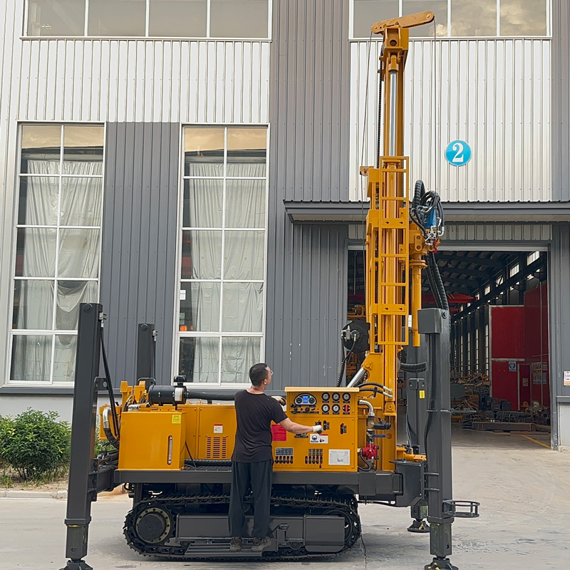
How far the documentation can support, and what still needs to be confirmed
Based on the verified documentation, the WR300SE is positioned for 300-meter-class conventional water well projects, with a maximum drilling depth of 300 m, suitable for loose formations and rock formations, an overall weight of about 7.2 T, a crawler travel speed of 2.5 km/h, a maximum climbing angle reference of 21°, and a hydraulic outrigger stroke of 1.5 m. This information supports placing it within the comparison scope of projects such as conventional farmland irrigation, rural water supply, livestock water use, and groundwater investigation, but does not constitute a conclusion of suitability for any specific project.
Items that need separate confirmation include: the aquifer depth and formation combination at the project location, the hole diameter corresponding to the completion structure and designed water yield, the actual selection of air compressor and mud pump, the matching of drill pipe length and transportation conditions, and the power derating requirements under high altitude or special climate. The influence of downhole tool combinations and drilling angle differences on efficiency, which are not covered in the documentation, should also be based on on-site conditions.
Only by reading the two lines of power and hole diameter as "configuration orientation" rather than "capability ranking" can the judgment be implemented: the hole diameter is first determined by the well completion design, then the power is selected according to the actual load of the hole diameter, formation, and altitude, and the supporting conditions beyond the two lines are checked simultaneously. Taking any single line as large does not mean the project will go more smoothly.